Circuit description
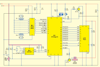
Fig. 1 shows the circuit diagram of the remote-controlled real-time clock with device controller. It comprises six sections, namely, IR detector remote control sensing and decoding unit, realtime clock, LCD interface, device switching unit, microcontroller and power supply unit The microcontroller unit integrates all the sub-systems and system software operates the system. Fig. 2 shows the circuit of the device controller. Remote control section. This circuit makes use of a Philips TV remote for device switching and RTC parameter setting. It uses RC5 coding format, which is also known as ‘biphase coding.’ In RC5-coded signal, each bit has a uniform duration.
Circuit diagram
the power layout
PARTS LIST
Semicondutors:
IC1 - Atmega16 AVR
microcontroller
IC2 - DS1307 real time clock
IC3 - TSOP1738 IR receiver
module
IC4 - ULN2803 darlinton array
IC5 - 7805 5V regulator
IC6 - 78012 12V regulator
T1, T2 - SL100 npn transistor
BR1 - 1A bridge rectifier
- LCD module (16×2)
Resistors (all ¼-watt, ±5% carbon):
R1, R3, R4,
R6, R10 - 10 kilo-ohm
R2 - 220 ohm
R5,R9 - 120 ohm
R7, R11 - 2.2 kilo-ohm
R8 - 330 ohm
VR1 - 10 kilo-ohm preset
Capacitors:
C1, C2 - 10μF,16V electrolytic
C3, C7, C8 - 0.1μF ceramic disk
C4 - 100μF,25V electrolytic
C5 - 1μF,16V electrolytic
C6 - 1000μF,35V electrolytic
Miscellaneous:
X1 - 230V AC primary to 15V,
500mA secondary transformer
S1 - Push-to-on switch
PZ1 - Piezo buzzer
XTAL - 32.768 KHz crystal
RL1-RL8 - 12V, 1C/O relay


No comments:
Post a Comment
Like and Share this post on Facebook