

Showing posts with label Audio and Amplifiers. Show all posts
Showing posts with label Audio and Amplifiers. Show all posts
Wednesday, December 5
PHASE-SHIFT OSCILLATOR
This circuit uses a simple RC network to produce an exceptionally shrill tone from a miniature speaker. With the
parts values shown, the circuit oscillates at a frequency of 3.6 kHz and drives a miniature 2-1/2" speaker with
ear-piercing volume.
The output waveform is a square wave with a width of 150 us, sloping rise and fall times, and a peak-to-peak
amplitude of 4.2 volts (when powered by 9 volts). Current drain of the oscillator is 90 mA at 9 volts, and total
power dissipation at this voltage is 0.81 watt, which is well below the 1.25 watts the 14-pin version will absorb
(at room temperature) before shutting down.
Circuit Diagram


LOW-IMPEDANCE MICROPHONE PREAMP
This amplifier uses a common-gate FET amplifier to match a low-Z microphone.
Circuit Diagram


GENERAL-PURPOSE PREAMP
This amplifier is useful for audio and video applications. Gain is set by Rf and the voltage gain of this amplifier is
approximately 1+Rf/560, where Rf is in ohms. Bandwidth depends on gain selected, but typically it is several
MHz. Rf=5.1 kW, which produces a gain of 10*(20dB) voltage.
Circuit Diagram


AUDIO DISTRIBUTION AMPLIFIER
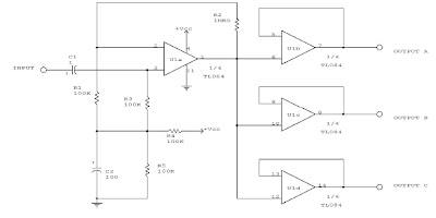
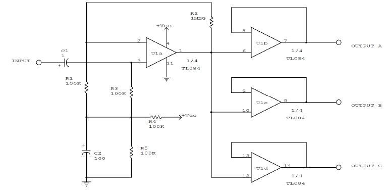
Three low-Z audio outputs are available from this circuit, using a quad TL084 FET amplifier. The input is high
impedance. Vcc can be 6 to 12 V for typical applications.
Circuit Diagram

LM380 PERSONAL STEREO AMPLIFIER
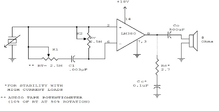
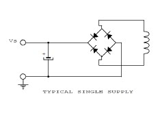
With the simple circuit, you can use your personal stereo to drive standard 8 ohm speakers. Use 2 identical
circuits to the circuit below:
Circuit Diagram

Circuit Diagram

BRIDGE AMPLIFIER
This circuit is for low voltage applications requiring high power outputs. Output power levels of 1.0 W into 4 ohm
from 6 V and 3.5 V into 8 ohm from 12 V are typical. Coupling capacitors are not necessary since the output dc
levels will be within a few tenths of a volt of each other. Where critical matching is required the 500K
potentiometer is added and adjusted for zero dc current flow through the load.
circuit


CHIME CIRCUIT
Resistor R1, capacitor C1, and two inverters from a square wave generator, which produces the basic tone. The
generator is followed by an inverter that acts as both a buffer and a driver for the speaker. Resistor R2, which
has a minimum value of 100 ohms, limits the current and controls the volume. Diode D1, capacitor C2, resistors
R3 and R4, and two inverters create the pulse generator that determines the turn-on and decay times of the
chime. The decay circuit-formed by D2, C3, R5, and Q-reduces the amplitude of the chime tone exponentially as
a function of time.
Circuit Diagram


SPEAKER AMPLIFIER FOR HAND-HELD TRANSCEIVERS
The LM383 is an audio-power amplifier that is capable of producing up to 8 W of audio output. R1 is essentially a
load resistor for the hand-held transceiver's audio output. R2 can be composed of two fixed resistors in a 10:1
divider arrangement, but using a potentiometer makes it easy to set the amplifier's maximum gain. When
powered from a vehicle's electrical system, the amplifier's +12V power source requires filter L1 to eliminate
alternator whine. The LM383 can be mounted directly on the heatsink because the mounting tab is at ground
potential.
Circuit Diagram


MINI-STEREO
This circuit is built around two chips: the MC1458 dual op amp, configured as a preamplifier, and the LM378 dual
4-watt amplifier. The gain of the preamp is given by R3/R1 for one side and R4/R2 for the other side, which is
about 100.
That gain can be varied by increasing the ratios. The left and right channel inputs are applied to pin 2 and 6. The
left and right outputs of U1 at pins 7 and 2 are coupled through C5/R10 and C3/R6, respectively, to U2 to drive
the two 8-W loudspeakers.
SPEAKER AMPLIFIER
Circuit Diagram


MICRO-SIZED AMPLIFIER
Sound detected by electret microphone MIC1 is fed to IC1's input through resistor R2, and capacitors C1 and C2.
Resistors R2 and R5 determine the overall stage gain, while C2 partially determines the amplifier's frequency
response. To ensure proper operation, use a single-ended power supply. R3 and R4 simulate a null condition
equal to half the power supply's voltage at IC1's noninverting input. The output of IC1 is transferred to emitterfollower
amplifier Q1 via volume control R6. The high-Z-in/low-Z-out characteristic of the emitter-follower
matches the moderately high-impedance output of IC1 to a low-impedance headphone load.
Circuit Diagram


GENERAL-PURPOSE PREAMPLIFIER
Suitable for general audio use, the preamp circuit uses a feedback pair. Current gain is set by the ratio of
(R4+R6)/R4.
Circuit Diagram


DC-STABILIZED FAST AMPLIFIER
This amplifier functions over a wide range of gains, typically 1 - 10. It combines the LT1010 and a fast discrete
stage with an LT1008 based dc stabilizing loop. Q1 and Q2 form a differential stage which single-ends into the
LT1010. The circuit delivers 1 V pk-pk in to a typical 75-ohm video load. At A = 2, the gain is within 0.5 dB to 10
MHz with the -3-dB point occurring at 16 MHz. At A = 10, the gain is flat(plus or minus 0.5 dB to 4 MHz) with a -3-
dB point at 8 MHz. The peaking adjustment should be optimized under loaded output conditions. This is a simple
stage for fast applications where relatively low output swing is required. Its 1 V pk-pk output works nicely for
video circuits. A possible problem is the relatively high bias current, typically 10 uA. Additional swing is possible,
but more circuitry is needed.
Circuit Diagram


20-DB AUDIO BOOSTER
The amplifier's gain is nominally 20 dB. Its frequency response is determined primarily by the value of just a few
components-primarily C1 and R1. The values in the schematic diagram provide a response of 3.0 dB from about
120 to over 20,000 Hz. Actually, the frequency response is flat from about 170 to well over 20,000 Hz; it's the low
end that deviates from a flat frequency response. The low end's rolloff is primarily a function of capacitor C1,
since R1's resistive value is fixed. If C1's value is changed to 0.1 mF, the low end's corner frequency-the
frequency at which the low end rolloff starts--is reduced to about 70 Hz. If you need an even deeper low end
rolloff, change C1 to a 1.0-mF capacitor. If it's an electrolytic type, make certain that it's installed into the
circuit with the correct polarity--with the positive terminal connected to Q1's base terminal.
Circuit Diagram


SUB-AUDIBLE TONE ENCODER
This twin-T oscillator produces six preset sub-audible tones from 93 to 170 Hz in three ranges.
Circuit Diagram


AUTOMATIC TAPE RECORDING
Amateurs don't have to miss the action while away from the rig. This circuit turns on a tape recorder whenever
the receiver's squelch is broken. After signal loss, the recorder will shut off following a slight delay.
Circuit Diagram


Subscribe to:
Posts (Atom)